


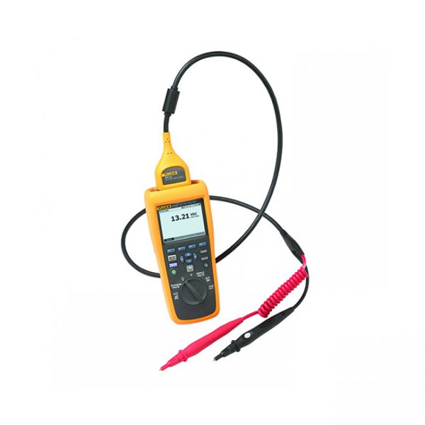
The Elektro EA-PS 9200-50 2U Programmable Laboratory DC Power Supply provides an output power rating of 0..3000 W with an output voltage of 0…200 V and an output current of 0…50A. It offers a wide AC supply voltage range: 90…264 V, with active PFC.
This microprocessor-controlled laboratory power supply comes with a clearly arranged control panel that features two rotary knobs, six pushbuttons, and two LEDs. Together with a color TFT display for all values and status, it simplifies the use of the device.
AC supply
This unit is provided with an active Power Factor Correction circuit and models up to 1.5 kW are even suitable for a worldwide operation on a supply from 90 V AC up to 264 V AC. With the 1.5 kW models, the output power is automatically reduced to 1 kW if the supply voltage is <150 V AC and with the 3 kW models is reduced to 2.5 kW at <205 V AC.
Power
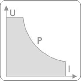
This unit is equipped with a flexible auto-ranging output stage which provides a higher output voltage at lower output current, or a higher output current at lower output voltage, always limited to the adjustable power set value or the rated power. Therefore, a wide range of applications can already be covered by the use of just one unit.
DC output
This model offers a DC output voltage of 0…200 V, an output current of 0…50 A, and an output power rating of 0…3000 W.
Current, voltage and power can be adjusted continuously between 0% and 100%, no matter if manually or remotely controlled (analog or digital). The DC output is located on the rear panel of the devices.
Discharge circuit
Models with a nominal output voltage of 200 V or higher include a discharge circuit for the output capacities. For no load or low load situations, it ensures that the dangerous output voltage can sink to under 60 V DC after the DC output has been switched off. This value is considered as limit for voltages dangerous to human safety.
Protective features
For protection of the equipment connected, it is possible to set an overvoltage protection threshold (OVP), as well as one for overcurrent (OCP) and overpower (OPP).
As soon as one of these thresholds is reached for any reason, the DC output will be immediately shut off and a status signal will be generated on the display and via the interfaces. There is furthermore an overtemperature protection, which will shut off the DC output if the device overheats.
Display and controls
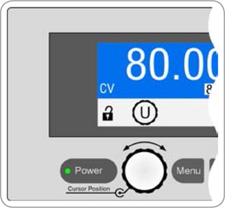
All important information is clearly visualized on a color TFT display. With this, information about the actual output values and set values of voltage and current, the actual control state (CV, CC, CP) and other statuses, as well as alarms and settings of the setup menu are clearly displayed.
In order to ease adjusting of values by the rotary knobs, pushing them can switch between decimal positions of a value. All these features contribute to an operator friendliness.
With a panel lock feature, the whole panel can be locked in order to protect the equipment and the loads from unintentional misuse.
Analog interface
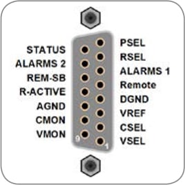
There is a galvanically isolated analog interface terminal, located on the rear of the device. It offers analog inputs to set voltage, current and power from 0…100% through control voltages of 0 V…10 V or 0 V…5 V. To monitor the output voltage and current, there are analog outputs with voltage ranges of 0 V…10 V or 0 V…5 V. Also, several inputs and outputs are available for controlling and monitoring the device status.
Digital interfaces
All EA-PS 9000 2U models feature two galvanically isolated, digital interfaces by default (standard: 1x USB & 1x Ethernet, with option 3W: 1x USB & 1x GPIB), which are located on the rear side. USB and Ethernet can be used to control and monitor the devices either with SCPI language commands or ModBus RTU protocol, while with GPIB only SCPI is supported.
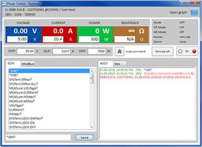
Software and programming
For remote control from a Windows PC, there is a software EA Power Control included with the device. It can be used with multiple different or identical models of series EA-PS 9000 2U to monitor and control the units. The software furthermore includes a firmware update tool, as well as a feature to record data and to control the units by a semi-automatic table processing.
For even more sophisticated, customer-specific applications there is complete programming documentation and also LabView VIs for direct implementation available.
All models of series EA-PS 9000 2U support the common command language SCPI and the ModBus RTU protocol via Ethernet and USB. Models with option 3W can only use SCPI via the GPIB port.
Remote sensing
Remote sensing can be done via a dedicated input which is directly connected to the load equipment, in order to compensate voltage drops along with the load cables. The power supply detects automatically whether the sensing input is connected and will stabilize the voltage directly at the load. The connection for the remote sensing is located on the rear of the device.
Options
Three-way interface (3W) with a rigid GPIB port installed instead of the default Ethernet port.
Manuals/Guides
Manufacturer Specs
| Model: EA-PS 9200-50 2U Specifications | |
| Product Type | DC Laboratory Power Supply |
| Housing | 19″ rack |
| Voltage (U) | 200.00 |
| Current (I) Ampere | 50.00 |
| Power (P) Watt | 3000.00 |
| Resistance (R) | No |
| Characteristic Curve | U/I/P autoranging |
| Human Interface | Graphicdisplay & Menue |
| Ext. control – analogue 0-5V/0-10V | Yes |
| External control – GPIB (IEEE488) | No |
| External control – USB | Yes |
| External control – RS232 | No |
| External control – CAN | No |
| External control – LAN | Yes |
| External control – Profibus | No |
| External control – DeviceNet | No |
| External control – Modbus TCP | Yes |
| Function generator | No |
| Special feature – High-Speed | No |
| Special feature – Sink | No |
| Special feature – water cooled | No |
| AC Input | |
| Input voltage | 180…264 V AC, 50/60 Hz |
| – with additional derating | 180…207 V AC |
| Input connection | 1ph (L ,N, PE) |
| Input fuse (internal) | T16 A |
| Leak current | < 3.5 mA |
| Power factor | ≈ 0.99 |
| DC Output | |
| Max. output voltage UMax | 200 V |
| Max. output current IMax | 25A |
| Max. output power PMax | 3000 W |
| Max. output power PMax with derating | 2500 W |
| Overvoltage protection range | 0…220 V |
| Overcurrent protection range | 0…55 A |
| Overpower protection range | 0…3300 W |
| Temperature coefficient for set values Δ/K | Voltage / current: 100 ppm |
| Output capacitance | ≈1600 μF |
| Voltage regulation | |
| Adjustment range | 0…204 V |
| Accuracy (1 (at 23±5 °C / 73±9 °F ) | < 0.1% UNom |
| Line regulation at ±10% ΔUAC | < 0.02% UNom |
| Load regulation at 0…100% load | < 0.05% UNom |
| Rise time 10…90% ΔU | Max. 30 ms |
| Display Accuracy | ≤ 0.2% UNom |
| Ripple | < 164 mVPP < 34 mVRM |
| Remote sensing compensation | Max. 5% UNom |
| Output voltage fall time (at no load)after switching DC output off | Down from 100% to <60 V: less than 10 s |
| Current regulation | |
| Adjustment range | 0…51A |
| Accuracy (1 (at 23±5 °C / 73±9 °F ) | < 0.2% INom |
| Line regulation at ±10% ΔUAC | < 0.05% INom |
| Load regulation at 0…100% ΔUOUT | < 0.15% INom |
| Ripple | < 6.5 mARMS |
| Display Accuracy | ≤ 0.2% INom |
| Transient time after load step | < 1.5 ms |
| Power regulation | |
| Adjustment range | 0…3060 W |
| Accuracy (at 23±5 °C / 73±9 °F ) | < 1% PNom |
| Line regulation at ±10% ΔUAC | < 0.05% PNom |
| Load regulation at 10-90% ΔUOUT * ΔIOUT | < 0.75% PNom |
| Display Accuracy | ≤ 0.85% PNom |
| Efficiency | ≈ 93% |
| Analog interface | |
| Set value inputs | U, I, P |
| Actual value output | U, I |
| Control signals | DC on/off, remote control on/off |
| Status signals | CV, OVP, OCP, OPP, OT, PF, DC on/off |
| Galvanic isolation to the device | Max. 400 V DC |
| Sample rate of inputs | 500 Hz |
| Insulation | Allowed float (potential shift) on the DC output |
| Negative terminal to PEMax | ±400 V DC |
| Positive terminal to PEMax | +600 V DC |
| Miscellaneous | |
| Cooling | Temperature controlled fans, front inlet, rear exhaus |
| Ambient temperature | 0..50 °C (32…122 °F) |
| Storage temperature | -20…70 °C ( 4…158 °F) |
| Humidity | < 80%, not condensing |
| Standards | N 60950:2006 + A11:2009 + A1:2010 + A12:2011 +AC:2011 + A2:2013EN 61326-1:2013-07 |
| Overvoltage category | 2 |
| Protection class | 1 |
| Pollution degree | 2 |
| Operational altitude | < 2000 m (6562 ft) |
| Digital interfaces | |
| Featured | 1x USB-B, 1x Ethernet (2, 1x GPIB (optional with option 3W) |
| Galvanic isolation from device | Max. 400 V DC |
| USB specification | USB 2.0, socket type B, VCOM driver |
| USB response time | SCPI: max. 5 ms, ModBus RTU: max. 5 ms |
| Ethernet specification | RJ45, 10/100 Mbit, TCP/IP, ICMP, HTTP, DHCP |
| Ethernet response time | SCPI: max. 7 ms, ModBus RTU: 9-17 ms |
| GPIB specification (optional) | 24 pin Centronics socket acc. IEEE-488, for standard GPIB cables |
| Terminals | |
| Rear side | Share Bus, DC output, AC input, remote sensing, analog interface, USB-B, Ethernet |
| Dimensions | |
| Enclosure (WxHxD) | 19“ x 2U x 463 mm (18.2”) |
| Total (WxHxD) | 483 x 88 x min. 535 mm (21”) (depending on DC out terminal type) |
| Weight | ≈ 15 kg (33 lb) |
| Article number | 06230215 |
Tech Specs
Power Supplies/DC Power Supplies Template |
|
|---|---|
| Outputs | Single |
| Max Voltage Output 1 | 200 V |
| Programmable | Yes |
| Max Current Output 1 | 50 A |
| Switching | Yes |
| Linear/Switching | Switching |
| Constant current/voltage | Yes |
| Remote Sensing | Yes |
Test Equipment General Attributes |
|
| Warranty | 24 MONTHS (2 YEARS) |
| Warranty Details | The warranty period is 24 months, beginning on the passing of risk. The warranty does not cover any product defects which are the result of incorrect installation, inappropriate use, incorrect operation, negligence, or other factors. |
| Interfaces I/O | Analog Output, LAN / Ethernet, Analog Input , Remote Sense, USB |
| Product Weight | 33 LBS |
| Product Height | 3.46 IN |
| Product Length | 21 IN |
| Product Width | 19.01 IN |
| Country of Origin | Germany |
| Shipping Height | 3.46 IN |
| Shipping Length | 21.00 IN |
| Shipping Width | 19.01 IN |


